How many types of drawings are there in drawing. F type Dashes THIN.

Engineering Drawings
K half section The view Obtained When the cutting plane goes half way across the Object to the centre line.
. In this type of section only half of the space or object is cut away. What is Full Section. Types of Section in Engineering Drawing.
A type Continuos Thick. They serve to present additional orthographic views of surfaces. A few of the more common ones are.
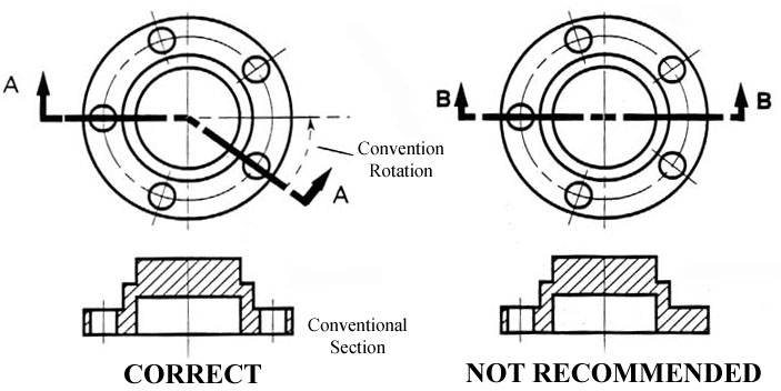
D type Continuous THIN Zig-Zag. Sectional views in engineering technical drawings Half Sectional views. Broken crosshatching shows where cutting plane line intersections material each material has its own crosshatching cutting plane line shows where the imaginery knife cuts thru the part line is always parallel to a line of rotation shows which cutting plane line goes to the section.
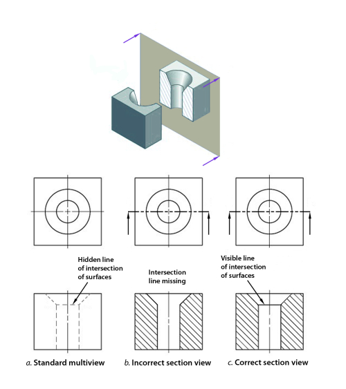
Figure 19 - Full and sectioned isometric views. The different line types are colored for clarity. Features that cannot be seen by hidden detail Cutting plane removes part section is what is left Cross hatching ois at 45 equispaced Centrelines often used for cutting planes Very thin sections not hatched eg.
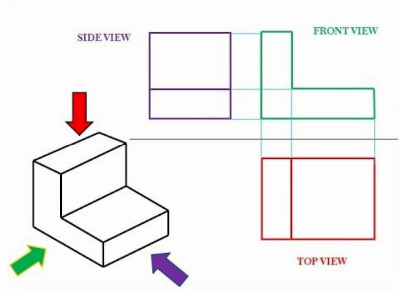
Here is an object sectioned from two different directions. In both cases the object should be standing on its base when the. A plan drawing is a drawing on a horizontal plane showing a view from above.
Magenta phantom line or cutting plane line. Engineering Graphics with AutoCAD 2011 1e James Bethune. Half sections or views.
What is Half Section. Full section in a full section the cutting plane line passes fully through the part. An elevation drawing is a view taken from a point outside the object without any slicing.
Full section The view obtained even the cutting plane is right across the object. C type Continuous THIN Freehand. 6 Types of sectional views Full sections.
There is no cutting plane line. The cut line is called a cutting plane and. You have learned that when making a multiview sketch hidden edges and surfaces are usually shown with hidden dash lines.
Offset View When specific features of an object that need highlighting are not located on the straight line of the cutting plane an irregular-shaped cutting plane is imagined cutting the object revealing the. E type Dashes THICK. Blue center line of piece or opening.
H type Chain THIN and THICK. Partial or Broken Out Section 4. Following are the different types of lines used in engineering drawing.
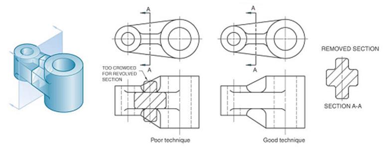
Section lines are used to define areas that represent where solid material has been cut in a sectional view. REVOLVED SECTION VIEW Revolved sections show cross-sectional features of a part. Here is an example of an engineering drawing an isometric view of the same object is shown above.
A few of the more common ones are. A cutting plane line shows where object was cut to obtain the section view. Section lines are evenly.
A section view is a view used on a drawing to show an area or hidden part of an object by cutting away or removing some of that object. This is the most common section called a full section with the imaginary laser cutting a line across. Red hidden line.
The cut line is called a cutting plane and can be done in several ways. Drawing Section Views What is a Section View. Further section drawings also provide information for the types of materials to be used in the construction.
As the name suggests the section drawings show the structure in a sliced form. A short series of lectures on Engineering Drawing as Part of ENGG1960 By Paul Briozzo. These lines are called section lining or cross-hatching.
A section drawing is a view taken after you slice an object then look at the surface created by the slicing. Half sections are commonly used to show both the internal and outside view of symmetrical objects. There are three major types of sections used in engineering drawing.
Plan Section and Elevation are different types of drawings used by architects to graphically represent a building design and construction. Black object line and hatching. A half-section is a view of an object showing one-half of the view in section as in figure 19 and 20.
Gaskets seals Do not show hidden detail in sectional view. What is a Section View. Types of section views 1.
This kind of construction drawing helps identify the primary structures in relation to other surrounding structures of the building. No need for additional orthographic views. G type Chain Thin.
A section is used to show the detail of a component or an assembly on a particular plane which is known as the cutting plane. There are three major types of sections used in engineering drawing. Plan Section and Elevation are different types of drawings used by architects to graphically represent a building design and construction.
There are a number of different types of sectional views that can be drawn. 81 and it is required to draw three sectional viewsAssume that you had a bracket and cut it with a hacksaw along the line marked B-B. Normally a view is replaced with the full section view.
A simple bracket is shown in Fig. A half section view is effective only on symmetrical objects and its main purpose is to show an objects internal and external construction in the same drawing. A section view is a view used on a drawing to show an area or hidden part of an object by cutting away or removing some of that object.
- इजनयरग डरइग म सकशन क परकर 1. Full sections half sections broken sections rotated. The following slides will help show the several methods or types of section views.
BROKEN-OUT SECTION VIEW A break line is used to separate the sectioned portion from the unsectioned portion of the view. An Elevation drawing is drawn on a vertical plane showing a vertical depiction. The diagonal lines on the section drawing are used to indicate the area that has been theoretically cut.
Sectional views are used in technical drawing to expose internal surfaces. Full section in a full section the cutting plane line passes fully through the part. 6 Types of sectional views Full sections.
Figure 20 - Front view and half section. A cutting plane does not necessarily need to cut the whole object. B type Continuous THIN.
Types of Section in Engineering Drawing. What is a section view in a drawing. A revolving view is effective for elongated objects or.
Break line is a thin continuous line and is drawn freehand. The lines are thin and are usually drawn.

Sectional Views
Engineering Drawings
Sectional Views In Engineering Technical Drawings
2
Sectioning Technique Engineering Design Mcgill University
Engineering Drawing Views Basics Explained Fractory

Sectioning Technique Engineering Design Mcgill University
Engineering Drawings
0 comments
Post a Comment